Laser Tracker and Robotic Total Station
Question: How Does a Laser Tracker Operate? Answer: A Laser Tracker is made up of two key components - the head unit and spherically mounted retroreflector. The head unit that contains a laser emitter that tracks in real time a Spherical Mounted Retroreflector (SMR) - typically a 0.500 or 1.500-inch diameter ball with mirrors fastened inside. The ball diameter precisely ground to a known diameter and the vertex of the mirrors are at the center of the ball. The laser tracker precisely measures 3D coordinates to the ball center nearly instantaneously. The first key is a clear line of sight is needed between the laser head and the SMR. A laptop is connected to the head unit that records the 3D positions of the SMR by measuring a distance along with elevation and azimuth angles. The laptop also runs specialty software that is used to fit the spatial data to various geometrical primitive shapes such as planes, cylinders, circles, lines, spheres, etc. The strength of a laser tracker is the accuracy and speed at which it takes measurements. Within confines of about 10 feet or less, measurement accuracy is on the order of plus/minus 0.001 - inches. It is important to note that with sensitive sensors needed to perform at such accuracies, things such as wide temperature swings, vibration, and direct sunlight can negatively affect the measurement performance of a laser tracker.
Question: How Does a Robotic Total Station Operate? Answer: Much in the same way a Laser Tracker does as described above - albeit about an order of magnitude less accurate. The strength of a Robotic Total Station is that is less susceptible to vibration, temperature variations, and direct sunlight when compared to a laser tracker. For longer distances, the robotic total station can outperform a laser tracker. Since the cost of the total station is about half that of the laser tracker, it costs less to operate which is in turn passed onto the customer.
Queston: What applications are best suited for Laser Trackers? Answer: Most any application requiring precise positioning. Examples of some the projects JMD Engineering has successfully completed are as follows:
Aircraft component location
Paper Mill Roller Alignment
Steel Mill Roller Alignments
Robotic CNC Tool Path Verification
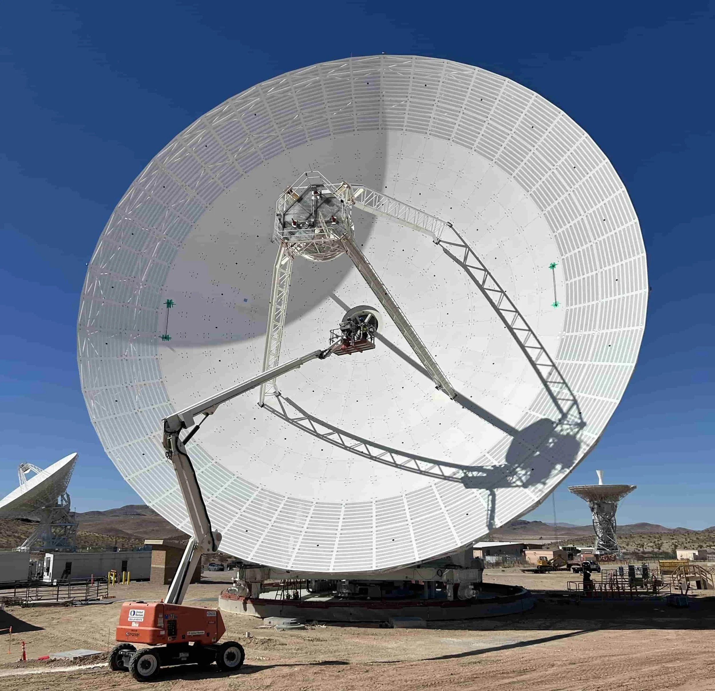
Precision Optical Equipment Location and Verification on Radio Telescopes and Earth Station Antennas
Jig and Fixture Verification and Adjustment
Field Machining Setup and Verification
Guide Rail Setup and Verification
Large Rotational Equipment Verification including Axis Features such as Plumb, Level, Orthogonality and Parallelism
Crane Slewing Ring Mounting Validation including flatness and concentricity
Question: What applications are best suited for Total Stations? Answer: As indicated previously, it primarily comes down to a question of required measurement accuracy. Generally speaking, measurements requiring accuracies of 0.020-inch or more are great candidates for a robotic total station. Examples of some of these applications are as follows:
Structural Steel Anchor Bolt layout and verification
Rough Alignment of Satellite Antenna Reflector Panels
Surveys of Autonomous Forklift Navigation Targets
Laser Tracker and SMR Distance Interaction
Laser Tracker Angle Encoders
Photogrammetry
Question: How does Photogrammetry Work? Answer: Reflective targets are placed on item to be measured. Typically, these reflective targets are 0.500-inches in diameter. In addition, unique patterns of reflective targes on a 5-inch square plastic backer plate are also placed on the item. These plastic backers are called codes. At least two scale bars with reflective targets are also placed on the item to be measured. These scale bars have precise lengths associated with each. A series of photographs are taken with a specialized camera. For larger items such as a 13-Meter diameter satellite, up to 150 digital photographs are taken at various positions covering the entire projection of the item to be measured. The digital photographs are processed through a specialized software that uses the coded targets to mosaic all the photographs together. The scale bars scale the resulting spatial data represented by the reflective targets into three-dimensional coordinates. Additional downstream processing of the data inserts coordinate systems and also has the capability for fitting into various geometric primitives such as planes, circles, cylinders, paraboloids, and even CAD data.
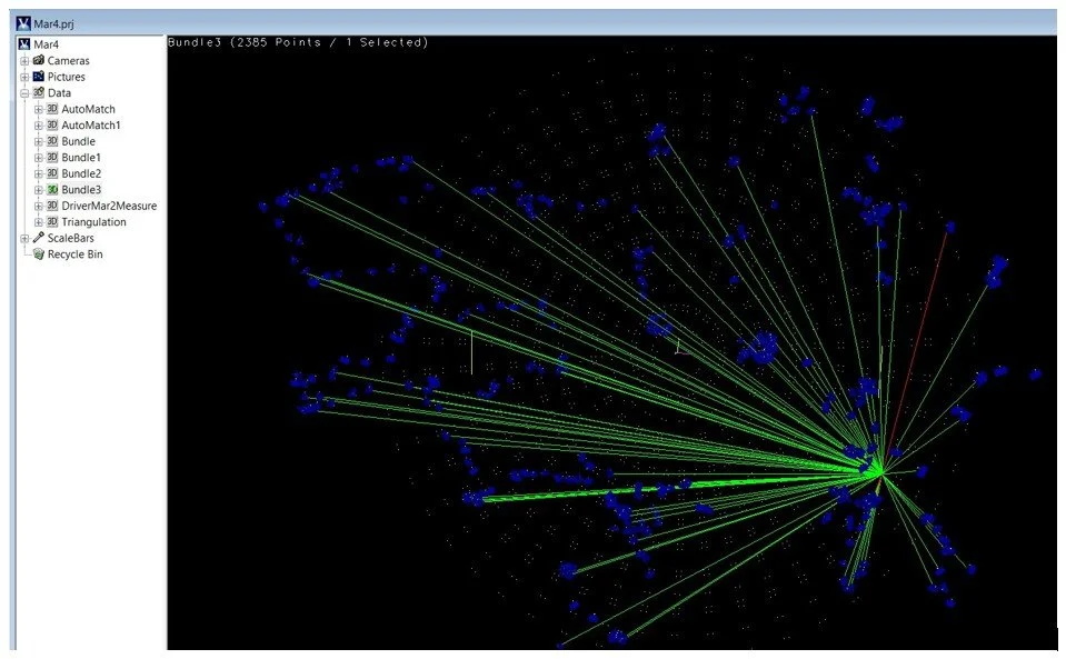
Representative Example of Multiple Cameras Recoding a Single point
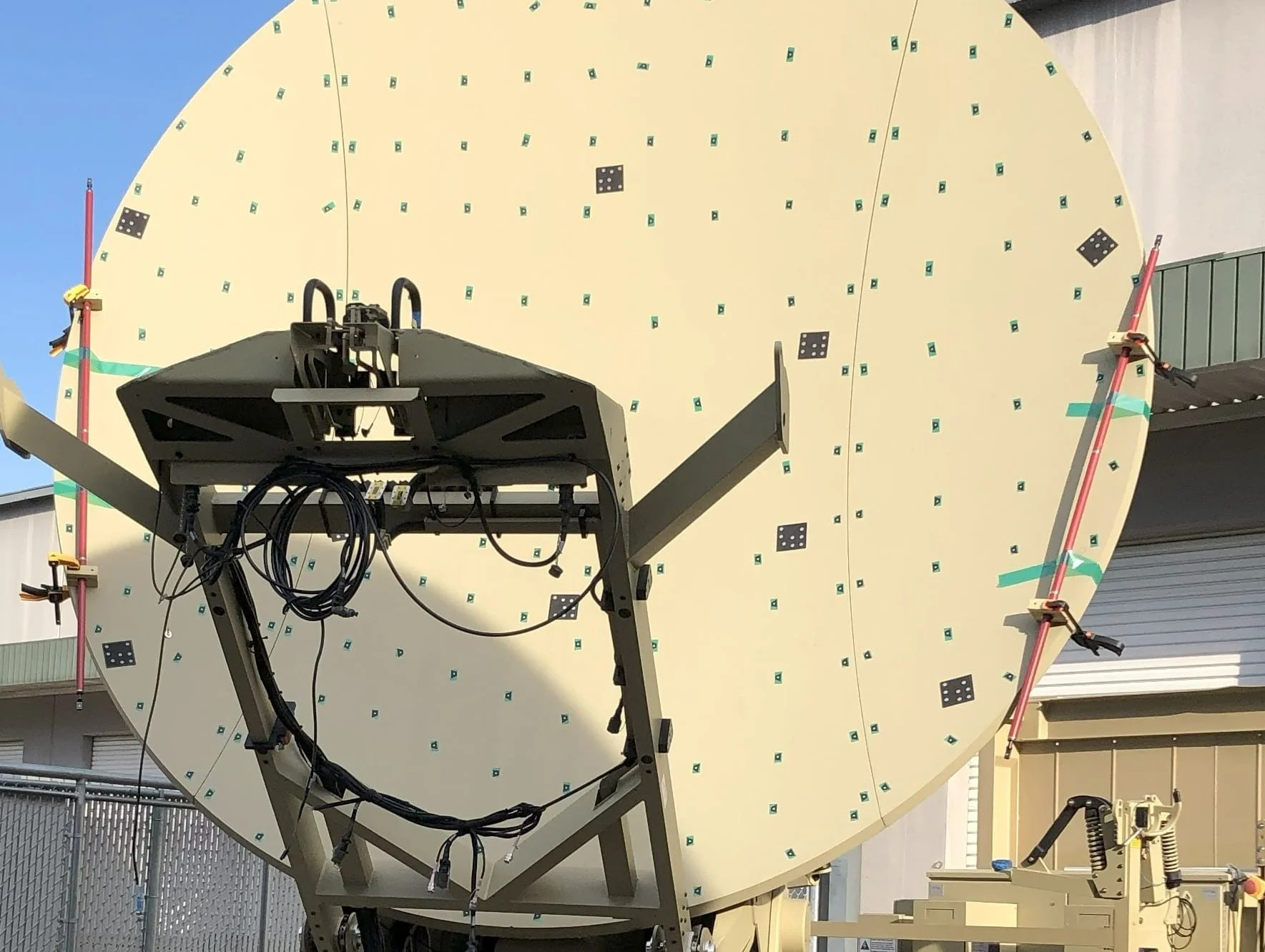
Targets, Codes and Scale Bars
Question: What type of objects are best suited for Photogrammetry? Answer: Large surfaces with gradual changes in shape are best suited for photogrammetry. Also, checking of large objects against a nominal surface or model lend themselves quite well to photogrammetry operations. Example of these are as follows:
Satellite Antenna reflective surfaces
Ship hulls and screws
Wind turbine blades
Large pressure vessels or containment structures
Scanning and Reverse Engineering
Question: What type of scanning processes do you offer? Answer: We have two different equipment offerings - one for small to car sized objects and one for larger objects. This first is a handheld unit connected by an umbilical to a high-performance laptop. This device uses blue laser technology and has accuracy to plus/minus 0.002”. The second is for larger objects which utilizes a class II laser and is accurate to plus/minus 0.012 inches.
Question: For a typical scanning project, what are the deliverable options? Answer: Listed in order of increasing cost, scanning deliverables are typically as follows:
STL files
NURB Surfaces
STEP Models
Associative Solid Models
STL files are the native output of most scanners. STL is a file format native to stereolithography CAD software. STL files can be easily exported into 3D printers and graphics software; however, it has limited use in most CAD packages as it cannot be manipulated. It is very difficult to do simple operations such as retrieving dimensions within nearly all CAD packages without expensive add-in. In simple terms, the point clouds generated by scanners have all the points connected by triangle flat surfaces. These surfaces become the basis for the STL files.
NURB (Non-Uniform Rational B-Splines) Surfaces are an optional deliverable for scanning operations. These are typically generated when you have organic surfaces such as flowing shapes in a sculpture or feathers on a bird for example. Downstream specialized post-processing software is needed to generate and edit STL files to generate NURB surfaces.
STEP files are the next step above STL in the scanning world. STEP stands for Standard for the Exchange of Product Data and is considered an ISO standard. STEP files are used for facilitating the sharing of 3D model files across multiple platforms. Features can be selected and measured within STEP file, but very little editing can be done within those types of files. Some refer to the STEP files as “dumb” models meaning there is no associativity within the features of the model. Additional downstream processing of the STL is needed by secondary software for the generation of STEP files. They could contain prismatic features such as cylinders, planes, spheres, and cones and even portions of NURB surfaces. It’s not exactly a push button operation as many software vendors would lead you to believe. Depending on the complexity of the scanned STL file, a step file may take anywhere from hours to days to complete.
The fourth and most expensive deliverable is an Associative Solid Model. These can be in the form of a file native to name brand CAD modeling software such as SolidWorks or AutoDesk Inventor. These are files where all the features are fully editable through changes in embedded dimensions and geometrical constraints. Highly specialized software is required for generation of these types of files. If the scanned item is comprised primarily of prismatic shapes such as pipe flanges, or weldments made from structural shapes, the process is relatively easy. When the shapes become flowing like those in the fuselage of a fighter jet, the blades of a wind turbine, or the body of a high-performance sports car for example, the process is very labor intensive to create Associative Solid Models and is the most expensive option.
Satellite Antenna Consulting Services
Question: What type of Satellite Antenna Consulting Services are offered? Answer: JMD Engineering LLC has over 25 years of experience working in locations all over the world in the satellite earth station industry. Examples of past projects are as follows:
Relocation of 16.4M full motion antenna from Virgina to Western Australia
Upgrades of 13M antennas
Final Alignments of new antenna Installations ranging from 9M to 34M in size
Mechanical Alignments of a 34M at an undisclosed location outside the continental US
Reverse engineering of antenna optics on 9M through 22M antennas
Antenna Civil construction subcontractor oversight at an undisclosed location outside the continental US